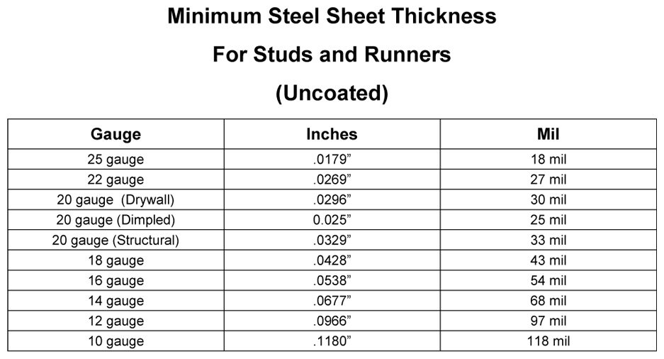
Bend Relief Size For 16 Gauge Sheet Metal
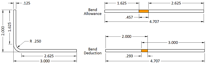
Bend Allowance Sheetmetal Me
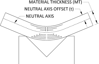
K Factor Sheetmetal Me
Sheet Metal Hems Sheetmetal Me

Sheet Metal Understanding K Factor
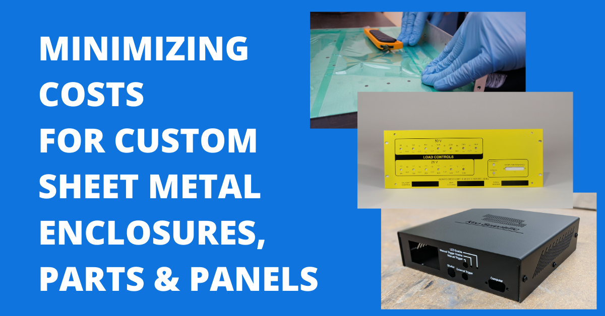
What Sheet Metal Shops Wish You Knew Reasonable Tolerances Grain Direction And The Base Flange
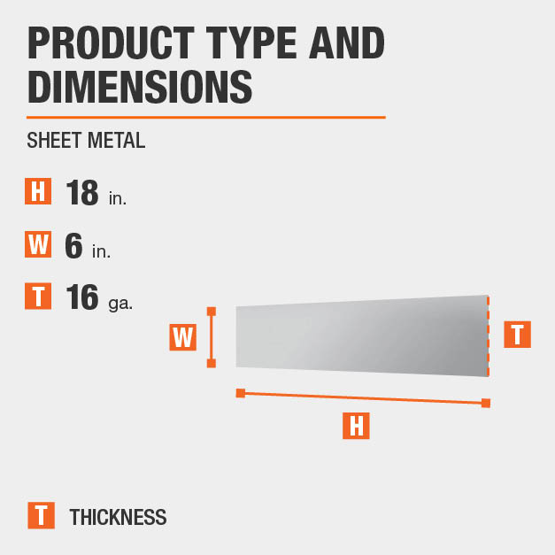
Everbilt 6 In X 18 In 16 Gauge Plain Steel Sheet Metal 801467 The Home Depot

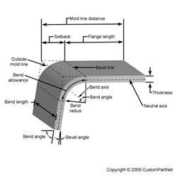
When the sheet metal is put through the process of bending the metal around the bend is deformed and stretched.
Bend relief size for 16 gauge sheet metal.

Sheet Metal Gauge To Mm Gauge To Thickness Chart Download Sheet Metal Is Metal Formed By An Industrial Process Into Sheet Metal Gauge Metal Gauge Sheet Metal

Pin On Tables Charts For Conversions Et Cetera
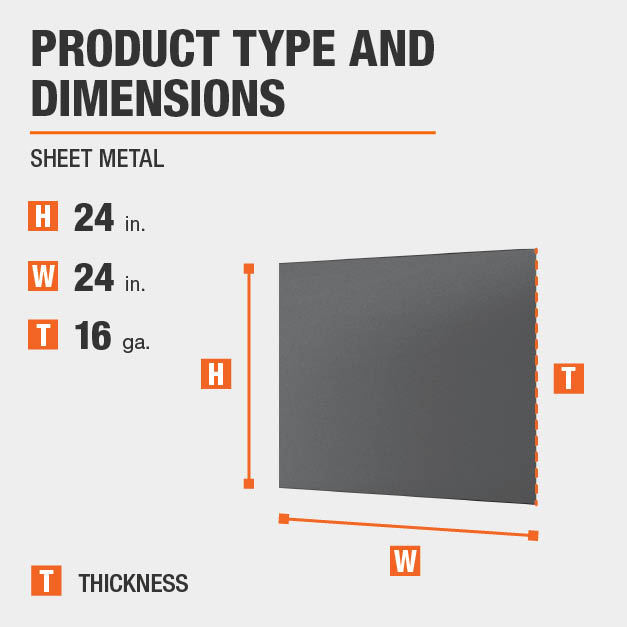
Everbilt 24 In X 24 In 16 Gauge Plain Sheet Metal 800657 The Home Depot

Sheet Metal Gauge Chart Sheet Metal Gauge Metal Gauge Sheet Metal
Bend Allowance Calculator

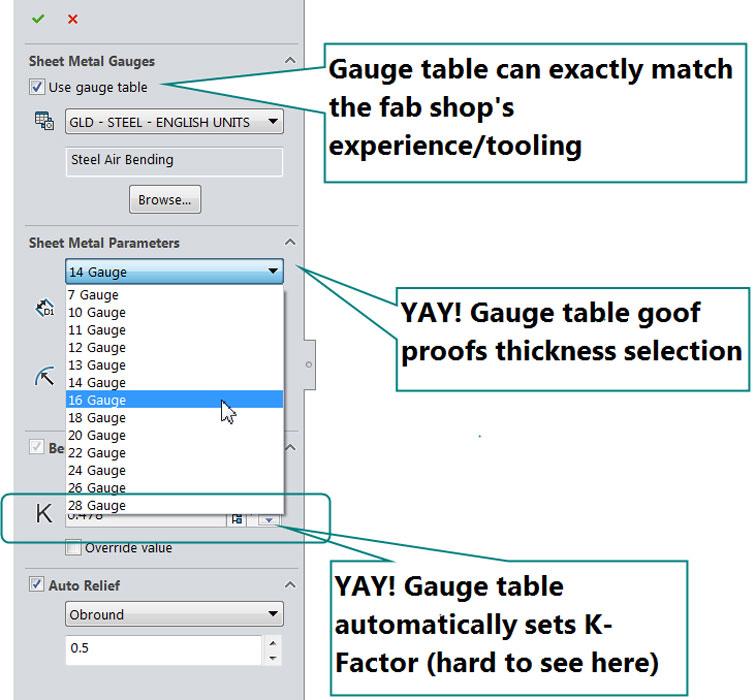
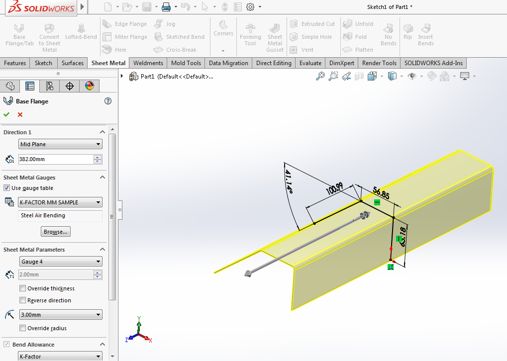
How To Create A Custom Solidworks Sheet Metal Bend Table
Sheet Metal Success In Solidworks Engineers Rule

Metal Gauge Chart Metal Gauge Steel Sheet Metal Stainless Steel Sheet Metal
16 Gauge Stainless Steel Sheet Metal 1 4306 Stainless Plate Buy 16 Gauge Stainless Steel Sheet Metal 16 Gauge Stainless Steel Sheet Metal Sheet Metal 1 4306 Stainless Plate Product On Alibaba Com
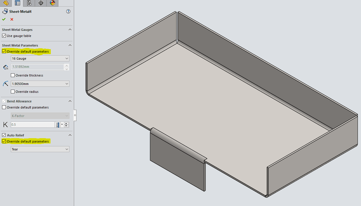
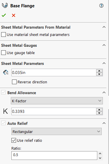
Solidworks 2017 Sheet Metal Options

Designing For Sheet Metal Fabrication White Paper

Solved Problem With Sheet Metal Corners After Adding Corner Seam With Overlap Autodesk Community Inventor
Solidworks Sheet Metal Gauge Tables Perception Engineering

How To Control The Warping Of Parts In Thin Sheet Metal Fabricating And Metalworking

Argentium Silver Sheet Metal Price Per 6 Jewelry Making Cleaning Jewelry Jewelry Making Supplies

B S Gauge To Mm Inches Conversion Contenti Gauges Size Chart Metal Art Jewelry Beads And Wire
Https Docs Plm Automation Siemens Com Data Services Resources Se 109 Se Help En Us Selfpacedext Pdf Mt01419 Pdf
Polyurethane Die Pads For Metal Forming Polyurethane Products
Https Encrypted Tbn0 Gstatic Com Images Q Tbn 3aand9gctf5 Nxksu4pilv5ywyfyl1 Wjg1jit Cavw4ekf14vx5cfm6oo Usqp Cau
Light Gauge Metal Stud Framing Buildipedia

Metal Cone Layout Google Search Geometri Tasarim Konteyner Ev

Box And Pan Sheet Metal Brake Manual Sheet Metal Bender Baileigh Industrial
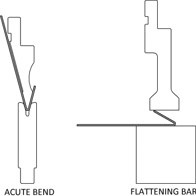
What To Do When Cutouts And Other Components Need To Be Placed Close To A Bend Protocase Blog

Pin On Tools For Metal Working
Source : pinterest.com
